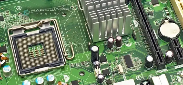
How to Diagnose Motherboard with Multimeter
Without the right tools, diagnosing motherboard issues can be frustrating and time-consuming. A multimeter is an affordable, versatile device that can provide valuable insights into potential problems. However, using a multimeter effectively requires an understanding of motherboard components and circuits.
Generally, a multimeter allows you to measure voltage, resistance, and continuity through different parts of a motherboard. By comparing your measurements to manufacturer specifications, you can isolate issues to specific locations. For example, incorrect voltages may indicate failing power regulation or shorts, while abnormal resistance can point to damaged traces or cold solder joints.
In this comprehensive guide, I will teach you how to safely use a multimeter to test for common motherboard faults. With some basic knowledge and the right process, you can quickly determine whether problems stem from the CPU, RAM, power supply, or the board itself. Let’s get started!
Prerequisites for Diagnosing Motherboards
Before jumping into measurements, you need the right gear and information. Here are some prerequisites for effectively troubleshooting motherboards with a multimeter:
- Digital Multimeter
Make sure you have a digital multimeter capable of measuring voltages, resistance, and continuity. Analog versions can work in a pinch, but digital ones provide more precise readings. Look for a meter with strong battery life, a clear display, and 4-20 range options for accuracy.
- Motherboard Manual
Reference documentation for your specific motherboard is mandatory. The manual provides key data like voltage tolerances, jumper settings, and trace layouts needed to interpret your measurements. Manufacturers like ASUS, MSI, and Gigabyte provide manuals online if you’ve lost your original.
- Anti-Static Precautions
Use anti-static gear like wrist straps, anti-static mats, and grounded workstations when handling motherboards and components. Electrostatic discharge can instantaneously damage sensitive ICs and traces. Better safe than sorry when working with hundreds of dollars of equipment!
Symptoms Of A Bad Motherboard
Determining if a motherboard is faulty can be tricky, but common symptoms include:
- Failure to Power On – No response when pressing power button points to power delivery issues
- Bios Error Messages – POST code beeps or debug LEDs indicating component detection failures
- Intermittent Crashes/Reboots – Unstable voltage or shorts causing system instability
- Peripheral USB/Ports Not Working – Likely damaged PCIe lanes or connectors
However, conclusive proof requires direct testing using a multimeter:
How to Motherboard Failure With Multimeter
Here is how you can diagnose your motherboard with a multimeter and confirm what is the root cause of the issue:
- Check standby 12V presence on 24-pin ATX connector with power off. No standby voltage implies catastrophic regulator failure.
- Power on and probe major voltage rails at CPU, RAM slots, and GPU connectors. Deviations beyond 10% tolerance or fluctuations between rails indicates power regulation issues.
- Perform continuity tests across data lanes like PCI-E slots, memory traces for missing beeps showing opens/shorts in paths.
- Inspect for burnt spots/scorch marks denoting dead shorts. Smell for odor indicating overheated components.
- Assemble external build, systematically swap verified RAM and GPUs. Failure crashing even with known-good parts confirms defective board.
While troubleshooting motherboards requires an understanding of voltage, resistance principles and layouts – methodical multimeter testing combined with inspection for physical damage can conclusively reveal faults. Knowledge of common failure symptoms also helps rule out software issues versus hardware defects.
Now Let’s Diagnose the specific issues of the motherboard with the multimeter.
Test the Power System
The first place to look when diagnosing motherboard issues is the power regulation system. If components are not receiving expected voltages, functionality will suffer. Let’s go through how to check the key power rails.
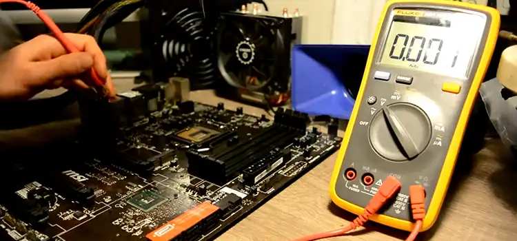
Step 1: Check the 24-pin Connector
This main power connector supplies multiple voltage rails from the PSU like +3.3V, +5V, and +12V that distribute power across the entire board.
- Set your multimeter to DC voltage mode, with a range between 20V DC.
- Probe the appropriate pins indicated in your manual for each rail one at a time, being careful not to short any pins.
- Compare readings to expected values, looking for anything 10% above or below specification.
- Faulty readings indicate an issue with the power supply itself or shorting further down the line.
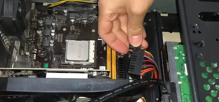
Step 2: Check the 4/8-Pin CPU Connector
This connector powers the CPU directly, with +12V and ground pins.
- Probe the designated pins with the multimeter set to 20V DC.
- Refer to your manual for pinout and exact voltage, as it may be slightly above or below 12V by design.
- Deviations outside of 10% indicate a problem with power delivery to the CPU socket.
Step 3: Check Voltage Regulator Modules
VRM’s convert high 12V/5V inputs to lower stable voltages for components like DDR memory or PCIe lanes.
- Locate VRM components and probe exposed test points shown in board documentation.
- Compare to specified voltages for those rails.
- Issues here mean localized voltage instability for attached devices even if the main connectors test fine.
Pay special attention to VRMs supplying the CPU, as inadequate power can lead to hard-to-diagnose crashes or freezes.
Test Continuity of Traces
While voltage checks power flow, checking continuity focuses on the physical connections tying everything together. Issues like short circuits, damaged layers, or cold solder joints can cause high resistance or disconnects resulting in erratic behavior.
- Step 1: Set your multimeter to continuity check mode, signified by an audible beep on detection.
- Step 2: Test connectivity by probing points along key data lanes like PCI-E and memory slots back to the CPU socket.
- Step 3: Check exposed solder points around peripheral connectors as well for things like USB ports or integrated headers.
- Step 4: Any missing beeps indicate breaks in continuity that require closer visual inspection to identify the fault location.
Pay special attention to traces around the CPU socket and chipset area, as these PCB layers experience significant stress from use and cooling solutions.
Isolate Issues through Selective Power Cycling
If you’ve found voltage or continuity issues, you can further isolate the location by powering up different sections of the board. This helps differentiate between failures on the board itself versus connected devices.
- Step 1: Disconnect storage drives, graphics cards, and other peripherals, only leaving the CPU, memory, and power connections.
- Step 2: Attempt to get video output from integrated graphics or use an external GPU.
- Step 3: If the system now boots, faulty components or PCIe slots may be to blame.
- Step 4: If issues persist, unseat memory modules one at a time to check if a specific stick causes problems.
- Step 5: Failures isolated to the motherboard alone indicate internal shorts you’ll need to inspect.
Leverage selective testing to pinpoint whether replaceable parts or the board itself needs repair. Just remember to discharge properly before swapping components to prevent ESD damage.
Analyze Readings to Determine Issues
With prerequisite knowledge and some diligent testing, you can now leverage your measurements to identify likely issues:
- Voltage Deviations: Fluctuations or drops can mean failing PSUs, VRMs, shorts, or inadequate connectors unable to supply components.
- Missing Continuity: Damaged layers or joints prevent communication between sockets and ICs necessary for normal function.
- Operational with Bare Minimum: If the board works fine with just CPU/RAM, other devices or slots may be compromised and require replacement.
- Persisting Problems: Shorts or component issues on the board itself rather than attachments if problems surface even with minimal config.
While the prospect of using a multimeter may seem intimidating to a beginner, motherboards are actually full of convenient test points once you understand the basics. So grab your multimeter, reference manual, and anti-static gear to tackle suspect motherboards with confidence! Just take it slow, double-check your connections, and interpret the measurements correctly.
How to Test for Short Circuits
A short circuit is an abnormal connection between two points in a circuit that results in excess and uncontrolled current flow. This can cause overheating damage, voltage drops, or component failure.
Here are the steps to follow:
Step 1: Set your multimeter to continuity check mode. This is usually indicated by a symbol.
Step 3: Power off the motherboard and discharge any residual electricity.
Step 4: Touch the black probe tip to the exposed ground on the motherboard, such as the metal casing of a screw port.
Step 5: Touch the red probe tip to various signal tracks and voltage delivery traces across the surface of the board.
Step 6: Listen closely for any beeping sound, which would indicate an abnormal short circuit exists between the two points.
Step 7: Carefully work across the entire board, testing connectivity between various grounding points and exposed copper tracks that should not have continuity.
Step 8: Note any locations triggering the continuity beeper and visually inspect for debris or damage. Isolate and resolve before operation.
Finding shorts requires careful examination of board layouts and an understanding of normal conductivity paths versus anomalous connections. Isolate and resolve any discovered shorts before proceeding.
How to Test the Capacitors
Capacitors help smooth out voltage deliveries across the current-hungry components of the board. When they fail, you may experience crashes, blue screens, reboots, or voltage irregularities. The step to check capacitors using a multimeter is given below:
Step 1: Power off the motherboard and discharge stored energy.
Step 2: Inspect electrolytic capacitors near critical regulation areas for signs of bulging or leaking fluid.
Step 3: Set your multimeter to capacitance mode, usually denoted uF or similar units.
Step 4: Touch the black probe to the negative pin of a capacitor, and the red probe to the positive pin.
Step 5: Note the capacitance reading on the multimeter and compare it against the labeled rating printed on the side of the capacitor.
Repeat steps 4-5 to check capacitance for the major capacitors powering voltage regulation and delivery across the motherboard.
Keep in mind that capacitor lifespans are 5-10 years so boards older than this may need replacements due to age rather than visible damage.
How to Test the Voltages
In addition to visually inspecting capacitors, regulators, and MOSFETS, you can directly test delivered voltages at multiple points across the motherboard using your multimeter.
Steps:
Step 1: Consult motherboard documentation for diagrams of voltage test point locations.
Step 2: Power on the motherboard, allowing regulation circuitry to initiate.
Step 3: Set your multimeter to DC voltage mode in the appropriate 10-20 volt range.
Step 4: Make secure contact between the black probe and the exposed ground.
Step 5: Touch the red probe firmly to the specified measurement point for that particular voltage rail.
Step 6: Allow the reading to stabilize, and take note of the voltage shown on the multimeter.
Step 7: Compare the reading to the expected value from the motherboard manual, looking for variations greater than 10%.
Step 8: Repeat the process to measure critical voltage rails like 3.3V, 5V, and 12V supplied to CPU, RAM, and PCIe slots.
Step 9: Power cycle board between tests waiting for new stabilization.
Step 10: Make sure no extreme fluctuations occur at any point.
Pay particular attention to critical 12V/5V power supplied to essential components like the CPU, RAM slots, and PCI-Express connectors which are most sensitive to supply fluctuations.
How to Check Overall Condition
While testing focused power circuits provides insight into potential faults, assessing the overall motherboard condition helps determine if the operation seems normal or anomalous. Here are the steps to follow:
Step 1: Visually inspect the entire motherboard for damaged components or scorch marks.
Step 2: Power on and listen closely for any audible buzzing or whining from failing inductors.
Step 3: Run your hand firmly along the back side of the board feeling for hot spots away from expected warm areas.
Step 4: Enter the BIOS interface and check all monitored values like temperatures, and fan speeds fall into expected reliable ranges.
Step 5: Allow the motherboard to idle at the OS desktop for at least 15 minutes without any freezing, crashing, or reboots which would indicate instability.
Step 6: Consider trying to find a good replacement CPU and RAM to isolate issues further.
Step 7: Monitor overall operation for at least 24 hours under a moderate workload looking for any intermittent issues pointing to areas of failure.
Thorough testing increases confidence that an apparently functional motherboard will provide reliable service rather than acting intermittently or failing prematurely after reassembly.
Conclusion
I hope this guide has demystified using a multimeter to diagnose motherboard issues for you! Leveraging voltage, resistance, and continuity checking allows you to methodically narrow down problems to specific functional blocks. Comparing your measurements against manufacturer ranges quickly determines if power delivery or physical connectivity is compromised. Selective power cycling helps differentiate between board faults and peripheral devices.
While an advanced troubleshooting technique, the principles themselves are straightforward. With some diligent testing and interpretation, you can save money over blind parts replacement or avoid expensive electronics repair quotes. Just be sure to have the necessary manuals, take anti-static precautions, and don’t rush checks.
I welcome any questions below on the process outlined here! If you found this helpful, feel free to share it with fellow PC enthusiasts looking to level up their repair skills.
FAQ
What Are Some Safety Precautions When Using A Multimeter To Test Motherboards?
Some key safety precautions include:
- Wear anti-static gear like straps to avoid damaging sensitive components with ESD.
- Carefully probe pins to not accidentally short connections and fry board.
- Avoid touching board and meter probes at the same time for shock hazards.
- Double check meter is set to the correct range before probing the voltage.
Where Can I Find A Motherboard Pinout Diagram For My Particular Board Model?
You can usually find pinout diagrams and layouts in the support section of your manufacturer’s website. Look up your exact motherboard make and model to download the associated service or reference manual which will contain these diagrams.
What Tolerance Should I Expect When Checking Motherboard Voltage Rails?
In general, expect about a 10% tolerance, so if the documentation specifies 12V, any readings from 10.8V to 13.2V are likely fine. Refer to the exact tolerances for your model if provided. Significant deviations above or below thresholds indicate problems.
How Low Or Inconsistent Does Continuity Resistance Need To Be To Qualify As Good?
It depends a bit on the multimeter, but you’re looking for resistance values under 1 or 2 ohms in most cases. If you hear a steady audible tone when probing two points, that indicates solid connectivity through the trace or jumper. Intermittent beeping or high resistance implies breaks in the signal path.
How Can I Test Pcie Slots To See If They Have Any Faults?
Connect your meter to the PCIe slot power pins checking for 3.3V/12V/GND along with signal continuity. Install a known good GPU and try to boot. If GPU is not detected or the system is unstable, slots or lanes are likely compromised. Check other slots and general board functions to further isolate issues.
- Prerequisites for Diagnosing Motherboards
- Symptoms Of A Bad Motherboard
- Test the Power System
- Test Continuity of Traces
- Isolate Issues through Selective Power Cycling
- Analyze Readings to Determine Issues
- How to Test for Short Circuits
- How to Test the Capacitors
- How to Test the Voltages
- How to Check Overall Condition
- Conclusion
- FAQ
Subscribe to our newsletter
& plug into
the world of PC Hardwares

![[Fix] 2 Short Beeps and 1 Long Beep (100% Working)](https://www.hardwarecentric.com/wp-content/uploads/2022/05/2-Short-Beeps-1-Long-Beep.jpg)
